Michael E. Byczek
Attorney
Patent Law and Definitions
There are three different types of patents granted by the USPTO: Utility, Design, and Plant.
Utility
The definition appears in Title 35 of the United States Code Section 101: "Whoever invents or discovers any new and useful process, machine, manufacture, or composition of matter, or any new and useful improvement thereof, may obtain a patent".
An example of a utility patent is a tool, lock, engine, telephone, computer, online shopping procedure, video compression, software, medical device, and printer ink cartridge.
Utility patents last for 20 years.
Design
This refers to the ornamental design of a manufactured article (i.e. physical object).
Examples include the iPhone, a computer, automobile wheel, bottles, flashlights, and anything else that has a creative look and feel that visually distinguishes that object from other items.
Design patents last for 14 years.
Plant
These patents cover asexually or sexually reproducible plants and last for 20 years.
Laws, Rules, and Guidelines
There are three primary sources to understand patent law and prepare an application.
Title 35 of the United States Code is a federal statute that sets forth patent laws.
Title 37 of the Code of Federal Regulations are rules that elaborate upon federal laws.
The Manual of Patent Examining Procedure (MPEP) is a comprehensive set of guidelines used by patent examiners to analyze and review an application. The MPEP further defines what the laws and rules mean during the actual registration procedure.
The following excerpts from these three sources show how the same topic of drawings to be submitted with the application are explained differently and in more refined precision by the laws, rules, and MPEP guidelines.
Title 35 of the U.S. Code
Section 113: Drawings
The applicant shall furnish a drawing where necessary for the understanding of the subject matter sought to be patented.
Title 37 of the Code of Federal Regulations
1.84: Standards for drawings
(h) Views. The drawing must contain as many views as necessary to show the invention. The views may be plan, elevation, section, or perspective views. Detail views of portions of elements, on a larger scale if necessary, may also be used. All views of the drawing must be grouped together and arranged on the sheet(s) without wasting space, preferably in an upright position, clearly separated from one another, and must not be included in the sheets containing the specifications, claims, or abstract. Views must not be connected by projection lines and must not contain center lines. Waveforms of electrical signals may be connected by dashed lines to show the relative timing of the waveforms.
(1) Exploded views. Exploded views, with the separated parts embraced by a bracket, to show the relationship or order of assembly of various parts are permissible. When an exploded view is shown in a figure which is on the same sheet as another figure, the exploded view should be placed in brackets.
(2) Partial views. When necessary, a view of a large machine or device in its entirety may be broken into partial views on a single sheet, or extended over several sheets if there is no loss in facility of understanding the view. Partial views drawn on separate sheets must always be capable of being linked edge to edge so that no partial view contains parts of another partial view. A smaller scale view should be included showing the whole formed by the partial views and indicating the positions of the parts shown. When a portion of a view is enlarged for magnification purposes, the view and the enlarged view must each be labeled as separate views.
(i) Where views on two or more sheets form, in effect, a single complete view, the views on the several sheets must be so arranged that the complete figure can be assembled without concealing any part of any of the views appearing on the various sheets.
(ii) A very long view may be divided into several parts placed one above the other on a single sheet. However, the relationship between the different parts must be clear and unambiguous.
(3) Sectional views. The plane upon which a sectional view is taken should be indicated on the view from which the section is cut by a broken line. The ends of the broken line should be designated by Arabic or Roman numerals corresponding to the view number of the sectional view, and should have arrows to indicate the direction of sight. Hatching must be used to indicate section portions of an object, and must be made by regularly spaced oblique parallel lines spaced sufficiently apart to enable the lines to be distinguished without difficulty. Hatching should not impede the clear reading of the reference characters and lead lines. If it is not possible to place reference characters outside the hatched area, the hatching may be broken off wherever reference characters are inserted. Hatching must be at a substantial angle to the surrounding axes or principal lines, preferably 45 degrees. A cross section must be set out and drawn to show all of the materials as they are shown in the view from which the cross section was taken. The parts in cross section must show proper material(s) by hatching with regularly spaced parallel oblique strokes, the space between strokes being chosen on the basis of the total area to be hatched. The various parts of a cross section of the same item should be hatched in the same manner and should accurately and graphically indicate the nature of the material(s) that is illustrated in cross section. The hatching of juxtaposed different elements must be angled in a different way. In the case of large areas, hatching may be confined to an edging drawn around the entire inside of the outline of the area to be hatched. Different types of hatching should have different conventional meanings as regards the nature of a material seen in cross section.
(4) Alternate position. A moved position may be shown by a broken line superimposed upon a suitable view if this can be done without crowding; otherwise, a separate view must be used for this purpose.
(5) Modified forms. Modified forms of construction must be shown in separate views.
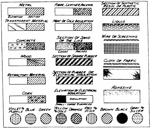
MPEP Chapter 600 (Parts, Form, and Content of Application) - Section 608.02 (Drawing) - Subsection IX (Drawing Symbols)
In utility patent applications, the following symbols should be used to indicate various materials where the material is an important feature of the invention. The use of conventional features is very helpful in making prior art searches.